Friday, October 30, 2009

Estimated completion December 2009

Seems like this is the never-ending project. All the small details keep getting finished, but it seems that as soon as one item is removed from the squawk list, two others take its place.


Following the completion of the gear door upgrade, we swung the gear to check the fit of the doors. All seemed OK, but when the gear reached the full up position, the gear circuit breaker tripped. Checking on the micro-switch adjustment, we found that the tab on the gear mechanism that operates the micro-switch was bent, allowing the gear motor to continue to run after the gear was up. So we installed a new tab.


The gyro panel is now complete and working. Since the Aspen EFD 1000 was originally installed, the units have been upgraded and Aspen is sending two new units to replace the original units. All at no charge to me (credit Aspen with GREAT customer support).

This photo shows the gyro panel with the pitot and static lines connected.

Much neater now that all the wiring has been tied in a harness and connectors added to allow servicing of the avionics without totally disassembling the panel.

The backup horizon is now installed and plumbed. This is the only vacuum instrument in the airplane.

My mechanic is feeling pretty good about the status of the project. He has been responsible for the manufacture of literally dozens of parts that are nearly impossible to find for this vintage aircraft. He is a true craftsman with aluminum.

Monday, September 14, 2009

Almost Done??!!


So Friday September 11 Aviation Research sent me some photos, shown above. It looks like the project really is approaching completion!!

Monday, September 7, 2009

A Two-Year Project


On Friday, September 4, I went to the Sandy River Airport to see about the progress on my airplane. The sight of the airplane sitting in the hangar by the door, looking for all the world like it was ready to fly, was exciting. It wasn't until I got to the airplane that I realized that a lot of work remains.


This photo shows the final stages of the construction of the wiring harness. The gyro panel is scheduled for installation later this month, and final testing should be completed by the end of the month. I had no idea that the addition of all the avionics would be so complicated. Aviation Research Systems continues to test and re-test every connection. All the wiring is tagged every 6" with a hot stamp identifying the wire and where it goes. Space for everything is at a premium and there is absolutely no more room to add anything (according to Bill, the avionics tech).


The Xerion engine monitor CPU mounts on the engine side of the firewall and has required the installation of multiple connectors (three, I believe) so that the inside display can be removed for service. Xerion was recently acquired by Ultra Electronics Flightline Systems. I can only hope that the support for this outstanding product will continue.

The above photo shows some of the many wires connecting the CPU to the display. There wires have since been routed through connectors to allow removal of the display if necessary.
The decision to add these connectors was fortunate, since the Xerion AuRACLE has recently been recalled for a system update.


I noticed that the fuel cap access panel had been removed, since the paint was missing from around the screws. Further investigation revealed that the old fuel caps have now been replaced with Aviation Research locking caps, as shown in the photos below.


Lifting the flap on the fuel cal reveals the high security lock.

Then simply turning the round key releases the latching mechanism...


Allowing the fuel cap to be removed.


Similarly keyed security locks have also been installed in the main and baggage doors.


With the installation of the special antennas for the Aspen PFD displays, the old rotating beacon was removed. It was not possible to re-install a beacon on the top of the airplane, so a new beacon/strobe was installed on the belly.


All the interior panels have now been replaced. The new panels, in the format of the Beech F33, will allow the upholstery shop to redo the interior quickly and easily. As a part of the interior work, special passenger reading lights were installed for the rear-seat passengers. The photo below shows the rough wiring for these lights.


For the first few months, I have elected to fly the airplane with dual controls installed. Ultimately I suspect I will replace the dual yoke with the single, throw-over yoke, but initial configuration with dual controls will make dual instruction easier. The main control wheel has multiple buttons and switches for easy access to frequent actions. The photos below show the final configuration of this wheel, which is now ready to install in the airplane.


An amazing number of wires will tie the wheel-mounted controls to the instrument panel. The pilot side yoke has controls for:
  • Push to talk
  • Control wheel steering
  • Autopilot disconnect
  • Electric trim
  • Transponder ident
  • Comm 1 frequency swap
  • ATC record
  • Digital recorder on/off


Here is a photo of the collection of wires to be terminated in a connector for the control yoke. Fortunately, when the controls are changed over to a single yoke, the connector will be identical and no additional wiring will be required.

And so the waiting continues.

Friday, June 5, 2009

Closer and closer...


Well, obviously the April first date was wildly optimistic. As of June 5, the airplane is still waiting for the installation of the instrument panel. The avionics technician has been struggling with the intricate complexity of making everything work together.


When first powered up, the Garmin GMX 200 failed to work, was sent back to Garmin for repair, and when re-installed still refused to work. Garmin and the technician are working to resolve the issue, and the solution appears to rest with Garmin. So we need to return the unit once again

The S-TEC 55X autopilot drew too much current, so it was also returned to the manufacturer in Mineral Wells, TX. No word on timing for the return.

In order to accomodate the new overhead air system, the old B35 interior upholstery panels are being replaced with the newer style F33A panels. This requires a lot of careful fitting, but will clearly be a good upgrade when finished.

Work on the iirframe is now essentially completed. The shop is in the final stages of installing the Rosen Visors, Security door locks, lockng fuel caps, and OSA temperature sensors.

The installation of the overhead air system is now complete. Beautifully fitted into existing overhead space, the air ducts do not intrude into the cabin.


The basic instrument panel, carefully fitted to the airframe, awaits the installation of the avionics and wiring harness. And yes, there are actually windows installed!


And now, the old N-numbers are gone and N1950B lives!


Installation of engine instrumentation and fittings is now complete. Notice the careful dressing of the wiring to maintain a reliable installation and neat appearance. Note also the reinforced oil access door.


The battery box and battery are now installed. When the master switch is thrown, things actually light up!

Thursday, April 16, 2009

Still waiting...

So here we are April 16. As best as I can determine, the airplane is no closer to flying now than it was a month ago. Wiring diagrams are still being developed, the avionics wiring harness is still on the test bench, and the mechanic is still installing the support rails for the upholstery. Work continues on the airframe and engine, with the engine monitor probes now installed. Sigh.
Chances of being done in time for the EAA fly-in in Oshkosh this July are looking slimmer and slimmer. My level of frustration is at an all-time high.

Thursday, March 26, 2009

Completion Approaches??

Well, nearly one month ago the prediction was that the airplane would be ready to fly by the end of the month. Here we are March 26, and the shop still thinks it will be ready for a first flight on April 4. Probably better than April 1...

The last items are arriving. We now have state-of-the-art Electroluminescent panels for lighting the switches and circuit breakers. A long, arduous path, but I hope well worth it.


The photo doesn't show the panel at it's best, but this is the only photo I have so far. The mechanics are hard at work, including weekends, and I am eager to visit next month. With luck, I may bring the airplane home.

Then the commissioning starts. This complex a project will require a detailed test procedure, something I am developing now. Every function needs to be tested and verified before the airplane goes in for painting and interior. I still hope that it will be ready for the EAA fly-in at Oshkosh this July.

Monday, March 2, 2009

Status March 2, 2009


Well, things continue to move slowly along. The wiring harness is nearly complete and should be tested this week. As the photos show, the AuRACLE engine monitor from Xerion has been installed, and the backup Horizon with related vacuum gauge is also mounted. By the end of this week, the wiring harness should be installed in the airplane.


Part of the challenge at this point in the project is making sure that every wire is properly terminated. The old wiring is being replaced throughout the airplane, and unfortunately the original identification on the wires has long ago been lost. This means that this is a two-person job, with each wire being identified and tagged before moving to the next task.

Monday, February 23, 2009

The High-Speed Gear Doors

The original plan was to add an after-market product from Precise Flight called Speed Brakes. This equipment allows rapid descent from altitude without shock cooling the engine. Fortunately, Aviation Research did the original certification of these speed brakes on the Bonanza and they shared their experience with me before I installed them. On the older Bonanza, there is significant vibration when the speed brakes are deployed due to the wing design of the Bonanza. Jerry at Aviation Research advised me that I would be probably be happier with a kit to allow the extension of the landing gear at significantly increased airspeed. So the High Speed Gear Door kit was ordered and installed. Little did I know that installing this kit is a major project.
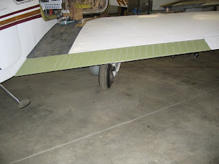
So many days later the new gear doors are fitted and installed. With this modification, I will be able to extend the landing gear at 145 MPH (125 Knots), with a placarded emergency gear extension speed of 175 MPH (150 Knots). The original gear extension speed was 123 MPH (105 Knots). Better than speed brakes and just as effective.

Interior Support Rails

In anticipation of the needs of the upholstery shop, Jerry at Aviation Research has been preparing the required support rails. The new interior will be modular, similar to more recent airplane interiors, and much easier to remove if needed to work on concealed wiring. The photos below show the new aluminum rail installed along the sidewall.

In the photo below, a temporary door panel has been attached to the support rail to check the fit. The entire process is extremely labor intensive and requires great attention to detail. But the final product should be worth it!


The Wiring Harness

It is now February 23, and the work oh-so-slowly continues. The incredibly complex wiring harness is expected to be finished this week and fully tested.


This photo shows the wiring harness in process. The connections and lacing are made on a mock-up of the actual panel, and then the entire harness is moved to the airplane.
This photo shows the mock-up from the front. The two Aspen PFD units are shown with the protective blue film. Once this is completed, all the avionics will be removed and transferred along with the complete wiring harness to the actual panel, which is presently mounted in the airplane.


Here is a photo of the new instrument panel installed in the airplane. By the end of this week, the new harness should be installed and the addition of the avionics will begin.

Tuesday, February 3, 2009

Status of the various projects

This posting includes photographs showing the status of the major work completed so far.

The left wing showing where the old "flying wing" stall indicator was removed.


The new stall indicator.


A new right flap assembly.


The new left aileron.


New aluminum honeycomb floorboards!


The "stinger" tail cone.


Polished stainless steel battery box, to be mounted on the engine side of the firewall. Also shown are the electrical solenoids, polished and ready to mount to the firewall.


The new instrument panel, mounted in the airplane and awaiting the final wiring harness and installation of avionics.

The repair where the old auxiliary fuel tank filler was removed.


The new outside air intake for the overhead air system.


More of the overhead air system.